Acorn Atom in FPGA
The project goal was to design and build a home-made computer
system using the VHDL language and an FPGA chip. Designing one
that is compatible with an existing machine avoids the need to
write and debug lots of software, and write lots of documentation
on how to program it. The ROM, RAM, and CPU were kept external for
reasons of efficiency, and analogue circuitry of course.
Everything else fits within the FPGA.
This project has had a lot of features done, and so I feel it is
okay to put details on the web. It is making progress in bursts
as I find time to do it. Most of the complexity lay in cloning
the 6847 video chip.
Primary Features
Secondary Features
|
 |
Prototype board layout
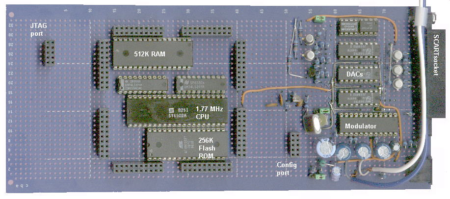
This board only exists to hold the ROM, RAM, CPU and some
video components. The bulk of the project is implemented inside
the FPGA of a BurchEd
B5 board, which plugs into it. You can see the date
code on the 6502A chip is 8251, making it over 21 years old, but
this CPU is still sold by Western Design Centre in speeds up to
14 MHz. I have some parts date coded 0250 and 0251,
i.e. 20 years later.
The project currently has 8K of firmware inside the FPGA, so
the Flash ROM is not used yet. The CPU could be put inside as
well, so a minimal version would need just the RAM chip!
The prototype originally used a real NMOS
6502A CPU, because implementing it inside the FPGA
adds to the experimentation cycle time. During development, I
wanted to test my design with a known-correct CPU. The 6502 is
still readily available and cheap, and uses silicon more
efficiently than an FPGA implementation. However, FPGA
implementation means you can dispense with finding a 6502 chip,
40-pin socket and soldering. Also, lower radiated noise higher
CPU clock rates may be possible since the CPU does not have to
drive PCB wiring capacitance. Real 6502 chips run from 5V, while
FPGA chips can runs as low as 1.8V for lowest power and high
speed.
I recently received a shipment of CMOS
W65C02S, W65C816S, and W65C22S
parts in both DIP40 and PLCC44 packages thanks to Mike Naberezny.
It is important to verify these chips work in this design,
because they are the only type of 6502 being manufactured these days.
There are some issues to address, such as minor pinout differences
that may prevent simple part swapping.
The logic signal levels may also be an issue.
The FPGA is rated to 3V3, and has clamping diodes so that pins
can be driven from 5V signals through a 100R series resistor
which limits the clamping current.
NMOS logic is roughly the same as 7400 series TTL, so logic high would be about 2V7 max.
CMOS pins may exceed this, and if so then 100R resistors will need to be fitted.
Alternatively the CPU VCC could be lowered to 3V3.
The Flash ROM chip is currently a 5V VCC part
and could theoretically drive the CMOS CPU data bus to 5V VCC,
but the FPGA has survived till now so the 65C02 may do as well.
The max CPU speed is declines as VCC is lowered.
The parts I have are marked -14 (i.e. 14 MHz at 3V3 VCC),
and the data sheet suggests this rises to 20 MHz with 5V VCC.
It may be wise to use 100R resistors by default,
to be cautious and to allow the CPU to run from 5V without
damaging the FPGA.
With a few minor modifications, the system is now running with a W65C02S.
A two-way KVM switch has made my desk less crowded
The CPU runs at 1.77 MHz (for PAL, or 1.79 MHz for NTSC),
matching the access rate of the video circuitry and thus allowing
their accesses to be interleaved for full transparent operation.
This has the major advantage that the CPU and VDU circuit can use
the same memory and have no screen disruption ('snow') during CPU
access. Since the CPU no longer has to wait for non-display
periods, it can run faster. Another bonus is that this clock rate
is nearly twice as fast as the original. Not quite as fast as the
BBC micro, but exactly as fast as an Atari 800XL. Without this
feature, the project would actually be harder to build. There is
only one downside, in that this may be a problem for software
requiring a 1 MHz clock. For example, those that use software
timing loops to set the speed of programs or generate precise
frequencies/periods on I/O pins. Such programs might include
those that generate music or EPROM programming pulses. Eventually
it was felt that the major advantages outweighed the
disadvantages related to a minority of programs.
Video circuitry
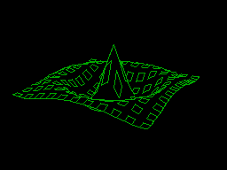
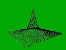
The original Atom had 256x192 pixels, allowing a 32x16 character screen with
8x12 pixel character cells. Although it isn't practical to provide 80-column text
which is common on terminals, many machines could display 40 columns in 320 pixels.
The Atari could provide 40 and 44 columns, so I added these display widths.
192 scan lines only allows 16 rows of 8x12-pixel characters.
I added the ability to use an 8x8 character font, allowing 50% more rows.
Not content with that, I also added a 240-scan line mode.
The new display modes are not known to the original firmware
which assumes a 32x16 character text screen. Likewise for new
graphics modes. New software must handle the new modes.
The prototype uses DAC and modulator chips that were readily
available in DIL packages. In a production model I would use more
highly-integrated chips such as those from Analog Devices Inc.
They make triple-video-DACs, video buffers and modulators, in
surface mount packages.
This converts the analogue RGB signals into Luminance and Chrominance signals,
suitable for S-video. This is the next best option of you don't have a SCART socket
on your TV. If you don't have S-video input, this chip also mixes Luma and Chroma
to provide Composite video.
Implemented in hardware to minimise software burden. The 16x16 pixel cursor is held in two bitplanes, allowing cursor pixels to be transparent, inverted, or either of two cursor colours. The cursor works indepently of the background, so it can even appear over a text mode screen.
This is a hybrid of software and hardware. Software is used for the complex initialisation, and hardware is used to receive data packets from the mouse.
This defines the colours for text, graphics, cursor, and border. One can do tricks like fading one screen out to black, then fading another screen in.
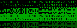
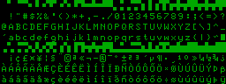
This has been improved to provide 256 programmable characters of 8x12 pixels.
An option register allows character set selection for the original Atom,
or an ISO-8859-1/ Unicode page 0 standard.
The former allows compatibility with existing software.
The latter allows it to display modern computer text.
This is pretty much essential for Internet based projects, such as TCP/IP and e-mail.
One can set the system to use attribute bytes to set the text to one of 8 colours, like so:
 |
The codes are designed to be compatible with teletext,
which assumes a black background. This was usual for computer terminals
when teletext was invented, because it reduced stress on monitors. |
 |
Today's computers tend to present documents as they appear on paper, i.e. a white background. |

| This presents a small problem for presenting documents with a white background.
The default teletext text colour is white, which will disappear!
Colours such as yellow show up poorly. One solution would be to darken the colours for white backgrounds,
and make white text black. |
 |
Another might be to use a light gray background,
as HTML does. |
Teletext screen
Acorn produced a VDU card for the original Atom.
It was based on the SAA5050 chip.
This provided 40-column text at PAL frame rates,
which was an improvement on the 6847 chip.
As a bonus, it allowed attributes such as colour and flashing.
At the moment, I'm not sure it is worth the effort to implement
because the system display logic already allows
40 column text at PAL rates.
The Atom firmware could be modified to take advantage of this.
Coloured text is now possible using the colour attribute codes.
This is enough to highlight headings, and hyperlinks.
Flashing text is not very useful:
it is used in HTML and teletext, but the Atom simply is not
capable of displaying the complexity of most web pages
and teletext is on most TVs already.
Reproducing the SAA5050 logic would be worthwhile in a BBC micro project.
For now, the basic colour attributes seem enough.
Furthe attributes can be implemented as and when required.
Not implemented
This required a bulky canned modulator.
RF modulation degrades the image a little, and isn't really worth providing
since most modern TVs have S-video or SCART.
Tape Interface
An analogue tape interface has not been implemented because
this requires a fair bit of analogue circuitry and there is not
much room left on the prototyping board (some parts of the
BurchEd board hang down into the spaces that are apparently free
on the prototype board). Tape interfaces were never very fast or
reliable, mainly due to the low fidelity of cheap cassette
recorders. Maybe minidiscs will be better. However, the digital
I/O pins are still implemented, so it should be possible to load
and save at digital levels. For example you could write a program
to use the PC printer port to load and save. This seems a
sensible option since most vintage software is obtained from the
internet and not on tape.
Floppy Disk Interface
Not implemented, for many practical reasons. FDC chips are
relatively hard and expensive to get, because the main market is
for PCs and FDC logic tends to be buried inside a surface-mount
PC motherboard chipsets. Old machines had many different disk
formats and sizes, so even if it happened to use the PC standard
3.5" drive, you probably would not be able to read it on a
PC. Writing a disk operating system to use PC-compatible disks
would be a lot of work, and unlikely to be used anywhere else.
There are more useful ways of providing PC-compatible mass
storage, such as a USB or memory card interface. USB could be
used to access USB floppy disk drives, available for notebook
computers (though quite expensive). There are also USB
Flash-memory devices the size of a key ring fob. These are a much
better idea because they are smaller, shock-resistant, and store
many times more than a single floppy disk.
Power consumption
Current budget is about:
  7 mA = CMOS CPU consumes less than 4 mA per MHz, thus about 7 mA at 1.77 MHz.
 20 mA = PS/2 mouse (figure from Microsoft Intellimouse)
 31 mA = Video modulator max.
 80 mA = RAM chip (specified for 65 mA typ, 80 mA max operating, 100 uA standby)
186 mA = Three video DACs at 62 mA max each
300 mA = PS/2 keyboard (official budget) in practice they usually draw much less:
	about 30 to 80 mA, and that is probably mostly for the 3 LEDs.
Current was measured at 440 mA at 5V without Flash ROM or keyboard attached.
The FPGA feels completely cold to the touch.
The RAM is run at less than max rated speed,
so probably consumes rather less than its 80 mA maximum
From the figures above one can see that current could be nearly halved by
discarding the analogue video parts. Using an LCD would allow this but consume current itself,
especially for the backlight.
Design size
Excluding ROM implemented on the FPGA, the design currently
uses about 1000 logic blocks.
Unexpected problems
There is a problem which appeared when the system was first
implemented. No sign-on message appeared. The address lines
suggested the CPU was trying to read the 6522 address repeatedly.
I disassembled a bit of the kernel and followed the start-up
path. When printing a character it tries to print to the printer
first. That routine sits in a loop while the printer is busy. So
I changed the write-character vector to skip the printer routine,
and the sign-on message appeared. I can only assume the real atom
data bus behaves differently when there is no chip driving the
data bus, and that the firmware relies on this. The real atom has
4k7 pull-ups on D3..D1.
Heirarchical organisation
Coping with complexity is an issue: the project became so
large it became vexing to find where problems lay. The design had
to be drastically reworked to have a heirarchical structure, to
keep things manageable. The video circuitry works fine, but the
CPU interface needs more debugging.
FPGA board modifications
The BurchEd board crystal had to be changed from 20 MHz to a
frequency related to the TV colour carrier. Although the BurchEd
board can be link-programmed for many frequencies, frequencies
that are not an exact multiple of the reference crystal have some
jitter. Sometimes this isn't a problem, but in this application
it is because it caused the screen image to jitter.
FPGA Upgrade
The B5 boards are now supplied with XC2S300 chips, which
provide 50% more logic and 12.5% more RAM. It is from the Spartan
2E family, so there are more ways to drive the I/O pins. The
design has been ported to the new device. This required minor
edits to the UCF, upgrading from WebPack version 3.3 to 4.2, and
solving some problems caused by expressions the new software no
longer accepted.
Current Status
The most recent working snapshot of the project powers up,
signs on, accepts characters from the PS/2 keyboard and runs
BASIC programs that are typed in. Video mode is
software-selectable. The video RAM start address is programmable.
The Atom's own beep routine works.
Everything is working apart from the tape interface. This is
reasonably satisfactory.
Firmware is embedded in mostly in the block memory of the FPGA
and partly in logic.
Bug fixes
Trivial changes to the VHDL code stopped the CPU working. The
logic is not significantly changed, but the internal layout
probably has. This may have pushed some timing detail beyond
required limits.
One important limit is the data hold time after clock phase 2
falls. This is about 10 ns for the 6502. ROM is selected by valid
address, which persists long enough to assert the select signals
during the data hold time. The working version selects RAM in the
second half of the CPU cycle, while phase 2 is high. Strictly
speaking this should cause failure, but in practice it has not -
so far. I suspected this might be the cause of the problem and
modified the VHDL code to improve it, but this change also
stopped it working. So the timing problem lies elsewhere?
This highlights the fact that it is not enough to think in
terms of code alone: you have to be aware of physical issues
within the FPGA. Projects eventually reach a size beyond which
you have to think as a hardware engineer.
To try to remove the possibility of internal data bus
conflicts, the single data bus has been split into two: one
driven by the CPU during writes, another multiplexing all the
data buses during reads.
When upgrading to the 300E, I had to upgrade the VHDL compiler
too. This failed to compile code that had been accepted by the
previous version. This was due to the compiler being stricter and
correctly rejecting 'X' (don't know) states in my address
decoder. The correct way is to use '-' (don't care) or avoid them
altogether. This tells the compiler to ignore them instead of
using 'unknown' values! The design is now robust to changes,
though all the mods I had tried have undoubtedly improved the
design.
The speaker worked when output bit toggled, but not when the
I/O port direction is changed. This was cured by making the direction bit
toggle the output bit.
Test switches
These controlled the video settings during video circuitry development
and before the CPU interface was present.
The video circuitry now seems stable so these switches have been removed.
The reset input is now a single pushbutton,
and the PAL/NTSC selection input is wired to a single link.
Current intentions
6522 VIA
This provides parallel I/O and timers.
It also has many complex features like
automatic handshaking for parallel I/O, and
being able to clock data in and out through shift registers.
These add a considerable amount of logic to write and test.
Fortunately MikeJ's Vic20 project had a 6522.
After small modifications this was incorporated.
BBC BASIC uses the 6522 but is currently having problems.
A minimal test program in Atom BASIC succeeded in
using timer 1 in free-running mode to generate
the 50 Hz interrupts that the BBC firmware requires.
This BASIC is a more sophisticated BASIC.
Firmware to RAM?
This is an alternative to firmware in Flash ROM.
Nearly a quarter of the available pins are used by the external
CPU's address (16), data (8) and control signals.
Many of these can be freed if the CPU is inside the FPGA and running the firmware from RAM.
This also requires the system to 'boot' the firmware to RAM
from an external ROM, but this could be a serial device using very few pins.
Future ideas
Audio DMA
Feeding data to a DAC thousands of times per second
is time-consuming for a CPU, so it is preferable to
have dedicated hardware to do this.
It can be fed from either a sound generator,
or a DMA engine sending samples.
Printer and Serial ports
Serial ports open up communication to modems and perhaps
the web. Quite what you would do is another matter, as the
Atom does not have the processing power, graphics ability or
software to run the popular internet applications. However,
you might be able to get the project to send (or receive?)
simple text emails. So if you have it doing some embedded
task, it could inform you as to progress when required.
The large size of the PC market makes it worthwhile for
chip manufacturers to produce high-integration devices like
the 16c552.
This provides two serial ports and one parallel port, all PC compatible,
in a single 68-pin PLCC package. There are other chips that have
two UARTs, but I don't know of any that throw in a printer port as well.
Another bonus is that the PC ports are very well known to many,
and there is a lot of example code for it. Code written for the PC
should require less porting effort than for other chips.
This has so much worth discussing it merits a section to
itself.
USB Interface
It is possible to put USB interface logic inside the FPGA.
There is an EDIF module available but without VHDL source. I
suspect this is non-trivial, consuming a third of an X2SC200.
Thus it is probably simpler and more economical to use a
dedicated USB chip.
The Cypress "EZUSB_80" chip might provide a
suitable interface. Note that it is an 80-pin surface mount
device.
Technically not too difficult to do, since the pixel data
signals are available at pins and suitable LCD control signals
would not take many more.
Economically it isn't so easy. QVGA colour LCD panels are affordable
in passive (STN) but this isn't fast enough to cope with
rapid screen changes - like motion or cursors).
There are some QVGA colour LCD in TFT, which is fast enough
but costs over twice as much.
C Cross-Compiler
This is the most common language for serious programming.
CC65 is a C compiler for machines with a 6502 processor architecture.
It has been ported to around a dozen machines ("targets") already,
but not the Atom or the BBC micro - yet.
Porting requires the creation of a block of code called
a "run-time library", containing the target-specific
fundamental functions. Kees van Oss has made a valiant start,
especially considering it is his first encounter with C.
In at the deep end, even for an experienced 6502 assmbly programmer like Kees.
Being a cross-compiler, programs have to be sent to the 6502 target.
Usually this is done by serial port, or sometimes disk.
32K over the PC serial port would take about 34 seconds at 9600 baud,
3 seconds at 115.2 kbaud, or half a second over this system's
parallel slave port.
Misc
The construction of the prototype was designed so that it
could be used to develop other 6502-based machines. The BBC
micro and the Oric for example. Jeri has made modifications
to the C1 so that it can be a re-usable platform as well.
This project and the C1 are complimentary rather than
competitive: the C1 packs as much as it can into the smallest
desktop PC motherboard form factor, and has 100's of Watts to
play with. My project explores what can fit into a Eurocard
format, and currently consumes 2.2 Watts!
Applications
Suggestions welcome! Mainly intended as a demonstration
project, it could also be used as a test bed for other
peripherals.
Credits
Many thanks to Jeri and Daniel for their correspondence in
this project, providing encouragement and technical suggestions.