More pictures
Timeline & people
Documentation
Firmware
Schematics
Specifications
Emulator Overview
Using the Monitor
Emulator Menus
Mini-Debugger
This page is an introduction to using the Acorn Monitor, running on the Emulator. It's not a 6502 programming tutorial – for more information on the 6502 try the World Wide Web. A good place to start is "http://www.6502.org; for a well-regarded tutorial, try the Incredible 6502 site.
Here you'll find:
- Using the Keyboard
- Resetting the 6502
- Displaying and modifying memory
- Entering and running a program
- Breakpoint and Resume
- Storing programs on cassette tape
- CUTS cassette tape data format
Using the keyboard
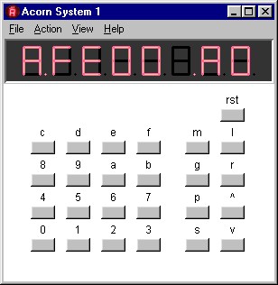
As on the Acorn Microcomputer itself, the monitor program can be run entirely by pressing the keys on the Acorn keyboard. These keys can be seen in the screenshot on the right, and are in three groups.
The 16 keys on the left are the hexadecimal keys (used for entering addresses and data); the 8 to their right are the command keys (described below), and the final key (rst) is the reset key (used to reset the microcomputer).
You can ‘press’ a key either by clicking on the buttons below the display or by using the corresponding key on the PC's keyboard. For the hexadecimal and command keys, use the character shown above the key (in either uppcase or lowercase). For the rst key, use the PC's escape key (Esc).
The Up and Down keys (^ and v) are heavily used, so you can also use the PC's Cursor up and down arrow keys for these, or the Enter key for Up.
Other options for controlling the emulator are available from the Menu bar, but all you need to use the Acorn Monitor are the keys just described.
Resetting the 6502
When the computer is first switched on (or the emulator is started)
the microprocessor is not running. Pressing the reset key
(rst) starts the processor running at the
start of the monitor program. After pressing the key, the display
should show a row of dots:

These indicate that the monitor has just been reset and is waiting for
a command key to be pressed.
Displaying and modifying memory
The 6502 processor has a 16-bit address bus; this means that it can read or write to any of 65,536 individually addressed bytes (addresses $0000 through $FFFF, where the ‘$’ indicates a hexadecimal number). This address space is often thought of as 256 pages, each of 256 bytes; that is, the top (left-hand) byte of the address describes the page, and the other byte addresses a particular byte in that page.
In the Acorn Microcomputer kit, the monitor is stored in Read-Only Memory (ROM) which uses pages $FE and $FF (that is, address $FE00 through $FFFF). You can look at its contents by using the modify command, the m key.
When you press the m key, the monitor acknowledges this by displaying A. followed by 4 hexadecimal digits, the current memory address. Initially these will be random, showing whatever happens to be in the memory storing that address.
You can now type in the digits of an address. These feed in from the right; if you make a mistake, you can just keep typing until the correct four digits are displayed. For example, try entering the address of the first byte of the monitor program (type: FE00).
Once the address is correct, the data (byte) at that address can be displayed by pressing the m key again, or by pressing either the Up or Down keys. This should display A0 on the right of the display, as shown in the first screenshot on this page.
You can now change the current memory address by pressing the Up key (to increase the address) or the Down key (to decrease the address); as the address changes, the data stored at that address is displayed. For example, the second byte of the monitor (at $FE01) is 06.
The modify command also lets you change memory, provided that the current memory address refers to a byte of Random-Access Memory (RAM). Unlike the monitor pages, RAM pages can be written as well as read, and in the Acorn System 1 they are located in pages $00 through $03. To modify a byte in memory, simply type in the new value using the hexadecimal keys while the relevant byte is being displayed.
Again, the digits of the new value feed in from the right. For example, try displaying the byte at $0030 (initially random) and changing it to A9.
Entering and running a program
Here's a short program, shown in hexadecimal on the left (the machine code) and in a more readable assembler code form on the right (with comments following the semicolons):
  A9 77        lda  #$77      ; LoaD Accumulator with $77
  20 60 FE     jsr  rdhextd   ; Jump to SubRoutine to copy
                              ; the accumulator to the display
  4C 04 FF     jmp  restart   ; JuMP to the monitor to continue
This program has just three 6502 instructions. The first byte
of each instruction is the operation code (often called
opcode), and the remaining bytes (if any) are data used by
the instruction.
The first opcode (A9) instructs the 6502 to load its accumulator (a one-byte temporary store located inside the microprocessor) with the byte immediately following the opcode (in this case 77). The assembler code for this instruction calls the operation lda (an abbreviation of ‘load accumulator’), and the operand for the instruction is indicated by the sequence #$77 (which means ‘the data will immediately follow the opcode and is the hexadecimal value 77’).
The second instruction jumps to a subroutine in the monitor program which takes the byte in the accumulator and prepares it for display. On return from that subroutine, the third instruction then jumps to the monitor to actually display the result and await more commands. Both these instructions are followed by the two-byte address to jump to (note that these have the low byte first and the page byte second, so the location named restart, for example, is at $FF04).
To run this program, first enter all eight bytes shown above, starting at location $0030. It's always a good idea to verify they are correct by re-displaying and checking them before trying to run the program.
Next, press the g (Go) key. The monitor will acknowledge this by displaying a stylized K. followed by 4 hexadecimal digits, the current go address. As with the modify command, these will initially be random.
You can now type in the digits of the address where your program starts (in this case, $0030). Once the address is correct, press g again to run the program; you should see the 77 appear on the display.
You might like to modify the byte at $0031 and run the program again, to verify that it works as expected.
Breakpoint and Resume
tbd
Storing programs on cassette tape
The tape Store and Load commands (s and l keys) let you store a program to tape (assumed to be an audio cassette) or retrieve it from a tape.
The Store command is initiated when you press the s key. The monitor then prompts (with S.) for the address of the first byte to be written to tape and then (with an underscore) for the address, plus one, of the last byte to be written. (For example, to store the first two bytes of the Monitor, the addresses $FE00 and $FE02 would be entered.)
After the second address is entered, pressing any command key causes the data to be written to tape (using the CUTS standard) at about 30 bytes per second (8.5 seconds per page). The display is blank while the data are recorded. The first Store address is updated (increased by one for each byte saved) during the store and is displayed when storing is complete.
To store to cassette using the emulator, first start the Tape recording (using the File menu or pop-up menu). This will prompt you for the name of a MIDI file to record to; when ready a red ‘recording’ lamp will be seen at the top left of the display. Then use the Store command as just described. While data are detected and the MIDI file is being written, the recording lamp shows a brighter red. Once the recorder has detected that no new data have been recorded for a second or so, it will stop recording automatically.
As an example, here's the MIDI file for a recording of the Monitor ROM.
The Load command is initiated when you press the l key. The monitor then freezes the display and waits for data from the tape; once this is received it reads it into memory, starting at the address recorded on the tape by the Store command. It indicates that data is being received successfully by writing each data byte (one bit per segment) ot the left of the display.
When using the emulator, initiate the Load command and then start the Tape playback (using the File menu or pop-up menu). This will prompt you for the name of a MIDI file to play back. Once selected successfully, a green ‘playback’ lamp will be seen at the top left of the display. After a short ‘lead-in’, the monitor should indicate the bytes being received as just described.
After playback is complete, the monitor will display the eight-dot ‘just reset’ display. If it does not (for example, if you do not start a valid playback file), you will need to reset the monitor using the rst key, as usual.
During both recording and playback the emulator will produce audible feedback of the tones being written to or read from the tape (provided you have a working sound card, speakers, etc.). To turn off the audio feedback, check the Tape Mute option in the File menu or pop-up menu.
CUTS cassette tape data format
The Computer Users Tape Standard (CUTS) was widely used in the 1970s (it was originally known as the Kansas City Standard and is also known as the BYTE standard).
The bits of data are encoded as audio waveforms on the tape. A logic 0 is recorded as 4 cycles of a 1.2 kHz tone, and a logic 1 is recorded as 8 cycles of a 2.4 kHz tone (the tones are sometimes pre-shaped so that on playback a square-wave is approximated).
A recording is started with a lead-in of the 2.4 kHz tone, and then each byte of data (8 bits, least-significant first) is preceeded by a zero (1.2 kHz) start bit, and is followed by a one (2.4 kHz) stop bit. Each bit lasts for 3.33ms, giving a data transfer speed of 30 bytes per second.
A block of data is recorded by first recording the To address (most significant byte first), then the From address (most significant byte first), and finally the data bytes (starting with the byte at the From address). The bytes recorded are those up to, but not including, the To address.
The Acorn System 1 uses division of the 1MHz processor clock by first 26 and then by 16 or 32 to generate the tones (see schematics).
In the simulation, a MIDI file is used to save the cassette output signal, using the notes D7 (2349Hz) and D6 (1175Hz) for the two tones (these frequencies are slightly different from those produced by the real hardware, but well within the variation to be expected on playback by contemporary cassette recorders). The size of the generated MIDI file is typically about 8KBytes for each page of 256 bytes saved.
Tone event timing is controlled by the Monitor program, and is recorded in the MIDI file to the nearest 0.1ms. Both recording and playback are synchronized to the emulator processor clock, so it is possible to halt the processor and single-step through the record and playback processes (while the processor is halted, audio feedback is also halted).