|
Adapted from Arduino Nut Blog - PL8-2 , dated 8 October 2009
see also http://arduinonut.blogspot.com/search/label/acorn atom Blog by Charlie Robson
AtoMMC 2.0
See the final version atommmc2 i.c. K.v.Oss
here of in NL
|
My children used to refer to C3PO as R2D2's dad. Funny how those minds work, isn't it.
I used to think that real fun could never be anything other than corporeal.
That just goes to show. This is the most fun that I've had in a while :) |
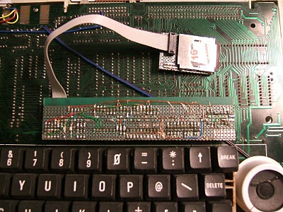
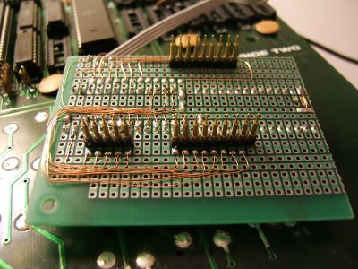
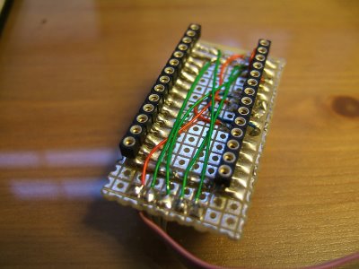
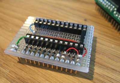
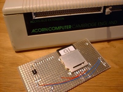
It's the V2 incarnation (can that be right? There's no meat here..!) of the PL8 MMC interface.
Here she is, in full component-side glory.
|
|
|
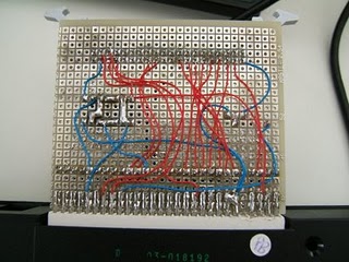
The TTL is a simple read/write decoder. The port onto which this fits
provides rough address decoding. I wish it would shave. I hate the chafing.
 |
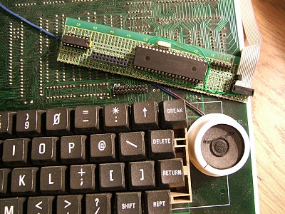
But I do so love the wiring.
It's a PIC - one of those manly sorts with the parallel slave port. I know
it's terribly incorrect to use the word slave - oops I used it again!
sorry! but that's just what it is. So the parallel slave port behaves
like a chunk of selection logic and wakes the PIC when a read or write
occurs. There are /RD and /WR lines.
The microcode on the PIC latches
data ready to be presented on a port when the /RD line is asserted. No
delay, it behaves just as a latch would.
Similarly asserting the /WR
line will latch the values present on the data bus to a register.
Interrupts ensure that these events are recognisable and the remainder
of the uC code is shuffling data to and fro.
The performance of this type of interface is already documented in another post <>
milliseconds to load programs <> so I won't go into it here.
Needless to say schematics and code, both micro and 6502, are available if you'd like them. |
|
The Atom needs some non-volatile random access storage. I ran out of
suitable patience burning EPROMs when updating the firmware for the new
MMC board. The old firmware was developed with the aid of an MMC
simulation that I shoehorned into the MESS emulator.
The simulator allowed me to code against a just-accurate-enough model
of an MMC card in SPI mode. The new interface doesn't have such a luxury
yet. So I got thinking, and decided that the 32kx8 FRAMs that I got
from Ramtron recently would do as an EPROM replacement. But I'd still need the
firmware in EPROM available to bootstrap from... Hmm. I'd also been
meaning to build a copy of a neat videoram replacement card that I found
in an Atom belonging to a friend. So that was that, really. |
 |
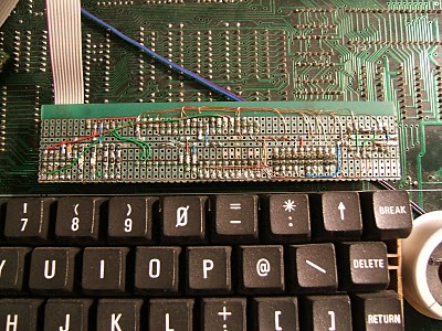
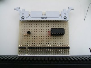
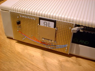
Or rather; At the moment it's only the video ram replacement side of the equation.
The flying lead takes A10,11,12 from the main board. The rest of the
signals are picked up from the vacated 2114 sockets. The empty socket is
going to take the FRAM and some decoding logic will live adjacent,
unless I can find suitable signals to pick up from the motherboard.
Not all underbellies are soft; This was quite hard, actually: |
|
It's a nonsense title for a post, but I was just thinking of Frankie Howerd.
I have a shameful admission. I lied in my last post, or at least mislead
you, dear reader. There were 5 projects - though I suppose the scale of
this one didn't really register on the need to win scale.
I made a mega-rom adapter for my Atom. I haven't inserted a large image for a while (Matron!), so here goes.
|
|
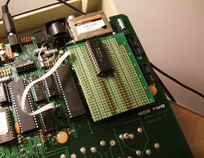
The mega-rom! In an Atom! It allows me to page in one of 16 4k images into
the address space allocated to utility software in the Atom's address
map. The switch carried with dignity at the end of the cable allows a
user to perform the magic. But you probably worked that out.
|
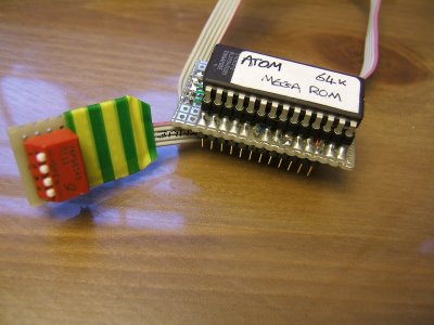 |
Don't you just love the green and yellow striped electrical tape? I was speaking to an
electronics fashion pundit at the RCM event and they told me (in the strictest confidence)
that this years projects simply must have green and yellow electrical
tape! Being the capricious sort that I am I simply have to agree, at least for today.
|
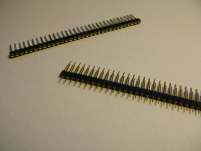
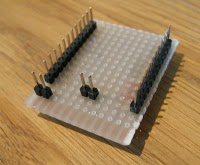
I have been expanding my horizons, not to mention my old computers - ha
ha, with contraptions such as this, fabricated with board spacers and
socket strip. These nifty connectors are ideal for making up adapters
like the one above. |
|
Pictured A board spacer is sized up by an interested socket strip I've tried a number of different makes but these are by far the best -
If I were Victor Kyam I'd buy the company. Which is SamTec if you're interested. No, I'm not receiving a back-hander.
Though if you're reading, SamTec - well let's just say I'm interested... ;)
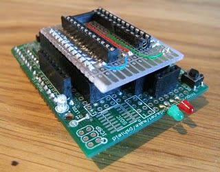
There is a slight wrinkle in the construction of these boards. The socket has
to be mounted on the same side as the pads. I've yet to find a supplier
of through-hole plated proto-board, but when I do I'll use it for this
purpose. In the mean time, I use one of two methods. The first involves a
'cost efficient' socket - the pressed pin variety. Splay its legs
akimbo and apply solder. Place it right-side-up on the padded side of
the (woeful , now I think of it) protoboard that my local electronics
supply chain provides. It rhymes with Craplin if you're wondering. Affix
to the board with a swift application of iron. Bingo! The 2532 adapter
for the tier jerker was manufactured using this method. Apply your eyes
to the previous post for a fine example.
The
second method, as used here, involves the socket strip. Place this
adjacent to the spacer, at chip's width naturally, and solder the pad to
the socket where it meets the board. You need a fine iron and a steady
hand for this so no beer or porn beforehand. Ooh which reminds me...
What?? Oh hush, I'm not soldering tonight.
|
 |
Here you see socket strip and spacer conjoined with solder bridges. Which are surprisingly hard to make intentionally!
Lordy I've wittered on long enough. I have an SD2IEC to attend to. Please excuse me :¬)
I couldn't make it work. I tried... Alas the Fail was strong in this one.
The spectrum wanted its CF adapter. I wanted to oblige. I tried a number of
different cards which all appeared to be lacking in Win. I had checked
over the wiring a number of times and, although not entirely convinced
it would help, I thus set about rewiring the beast.
Guess what! Still no Win. The board resolutely refused to
play nicely and so I took a step back and considered all the possible
failure points. Too much stray capacitance? A dry joint? Lack of
understanding? The list goes on. At last I decided to cut my losses and
re-work the board as an IDE interface. Several tens of minutes later,
having used an entire roll of desoldering wick, the board was bare but
for the edge connector. |
It's a good job
 |
The result"
|
|
Joy! I'd carefully checked each connection as it was made and I was certain
they were all good. I'm bouyed by the assurances of my meter, and sure
of at last securing a payment of success to offset the miserable week
spent futilely poking at the CF board. Apply power, insert device -..
Misery.
With heavy heart I put this project aside until some future time when I can
muster the strength of character to return to the joyless debugging. It
didn't get much better than this for weeks. I've started four more
projects since, each more resoundingly failful than the last!
So
that, dear reader, is why there have been no updates. I'm afraid I
don't have the strength of character to tell of my winless ways. I can't
even bear to tell you what they are. I do intend to return, though,
this time with bigger guns. More on that later.
What I needed was something simple to rejuvinate my mojo. To get me to the power-pill so I can start to chase those ghosts.
My
opportunity came at a recent retro-computer themed event where I met up
with a number of people thus far only identifiable by a 24x24 pixel
avatar and psychologically revealing nickname. Amongst these a contact
who keeps me fuelled with rare Acorn Atom goodies. In this case I was
knighted with a home-built rom-box, containing a couple of eproms.
|
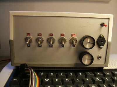 |
Forget the soviet nuclear-warhead launching switches! The mysterious dials and
socketry - this is truly a thing of beauty. But like most beautiful
things, it's what's inside that counts. And that was going to be ME. The
dumping challenge was on! [If you or someone you know built this
rom-box, then please get in touch!]
Once retrieved from the secure caress of their sockets the lovely ceramic
packaged gold legged EPROMS were quivering in the palm of my hand like
frightened baby Meerkats. These chips are ancient and JEDEC
incompatible. 2532s. 32Kbit arranged as 4K x 8. Here is the adapter I built to allow me to read the eproms using the glorious.
|
| |
And in situ:
|
As it turned out they contained images of programmers' toolkits. I must
admit I was hoping for a rare find, however the images in question are
already well known. But that is by-the-by. The thing is an hour had been
spent with a soldering iron, a further hour spent reconfiguring the
client application to draw the data PC-ward by the magic of electon in
serial cable, and then some moments of joy - as the contraption worked.
Worked?? WORKED!
I believe my drought is ended.
The rains of win are falling, filling drained butts of enthusiasm. I
shall venture forth and tackle the next item - Upgrading my SD2IEC in
order to take advantage of the JiffyDos-enabled commodore machines at my
disposal.. .
|
|
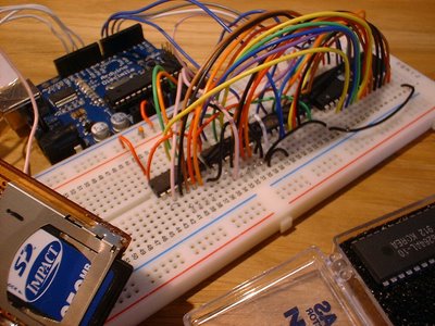
What a mess! But it works - sometimes :) All that stray capacitance - well someone's got to give it a home.
This is what I'm forced to do because the Stag PP39 EPROM programmer that I was so generously given by a fellow
FreeCycler works well, but for its serial connection. Ho hum. Wanting to burn an
EPROM to hold the driver code for the Atom MMC interface was the
necessity that was the mother of this frightful invention. In a fit of
pique I had the idea that I should create a 3-step process"Burn my
code into an EEPROM, transfer this to the programmer's buffer, and
thence into an EPROM! Why not just use the EEPROM for my project? An
astute question, esteemed reader. Well the type of EPROM expected by the
Atom is an olde-fashioned marque with a subtly different pin-out to the
more contemporary (read"standard) 27x series. Luckily the PP39 can
burn the 2532 that was required. Even luckier I suppose is the fact that I had one of
these! An adapter board can be made to facilitate the harmonious
interfacing of the disparate breeds, but this would involve less
lashing-up, you see? And we all need a jolly good lashing from time to
time.
|
|
I digress. What you see before you (or more correctly
above)
is an ls299 accompanied by a brace of ls164 shift registers. These in
turn are connected to an 8k Atmel EEPROM. In the driving seat you see
the Arduino and - naturally - a poor but functional MMC interface. The
164s are in charge of address generation, and the 299 has bi-directional
data line duties. It's a simple and effective design which I have
referenced before.
I've developed the Atom MMC driver in
assembler, naturally. This time I opted for cross assembly. If you saw
the code attached to my previous post (my - is that the time?) you may
well understand why - the inline assembler is hard work with its terse
labelling syntax. I develop and assemble on a PC, using a custom Visual
Studio workspace and a freeware 6502 assembler. The resulting binary is
debugged as far as possible using Wouter Ras' brilliant though tricksy
DOS Atom emulator.
When I'm happy with the code it gets put on the MMC card and burned to
the EEPROM using a subtle combination of swearing, crossed fingers and
sacrificial chickens. The burning process needs to be attempted a fair
number of times (the stray capacitance, bless) until the verify step
passes and I can be sure the lash-up has worked. Once transferred to the
programmer, the code fizzles its way onto a freshly UV-cooked EPROM and
then into its warm and welcoming bed - Socket IC24.
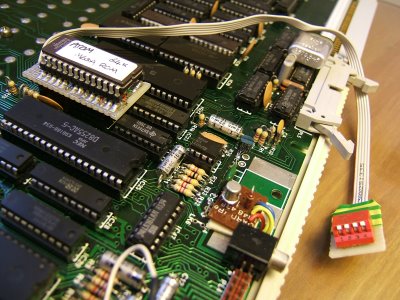
And so to work:
Presenting - the MMC adapter I built to fit on the venerable machine's expansion port, as visible here.
|
|
And in situ:
|
|
Goodness - that is
the time! Two and a half months this post has taken me! Either that or
my post-Sachertorte coma was deeper than usual... Whatever, forgive me. I
am off to play Atom Invaders - which now loads in under 3 seconds, a
far cry from the original 5 minutes of the tape version!
I'm getting back into the Atom swing! After a fruitless hour measuring
incorrect logic levels at the Atom's expansion port I was on the verge
of giving up. I had been prodding the VIA, according to available
documentation, and getting nowhere. All I wanted was a toggly bit. Was
that too much to ask for? That's when I decided to do some chip
swapping.
It takes me longer than most people to get to this point as I'm a software person at heart and so blame that first ;)
I
just happened to have a vintage 6522 VIA lying on my desk so I swapped
the chips over. Joy! I was flipping bits like a demon. Naturally my
thoughts turned to MMC...
10@=0
20!#208=!#208+3
30V=#B800
40W=#FFF4
50T=#80
60DIM LL(13),C(6)
70F.N=0TO13;LL(N)=#FFFF;N.N
80F.N=1TO2; DIM P(-1)
90P."PASS "N',$21
100[
110\ main
120:LL0 LDA @#0
130STA C+1; STA C+2; STA C+3; STA C+4
140LDA @#95; STA C+0
150JSR LL3
160LDA @#40+#0; JSR LL7
170LDA @CH"1"; SBC @0; JMP W
180\ select card
190:LL1 LDA @0; STA V; RTS
200\ deselect card
210:LL2 LDA @#20; STA V; RTS
220\ init hw and go spi
230:LL3 LDA @0; STA V+#C
240LDA @#FE; STA V+2
250LDA @#20; STA V
260LDY @10
270:LL4 LDA @#FF; JSR LL5; DEY; BNE LL4
280RTS
290\ xferbyte
300:LL5 STX T+0; STY T+1; LDY @8
310:LL6 PHA; AND @#80; STA V
320ORA @#40; STA V
330LDX V; AND @#BF; STA V
340TXA; ROR A
350PLA; ROL A
360DEY; BNE LL6
370PHA; JSR #F7FA; PLA
380LDY T+1; LDX T+0;
390RTS
400\ command
410:LL7 STA C+5; LDY @5
420:LL8 LDA C,Y; JSR LL5; DEY; BPL LL8
430:LL9 LDA @#FF; JSR LL5; AND @#FF; CLC; BPL LL10
440DEY; BNE LL9;
450SEC
460:LL10 RTS
470]
480P.$6
490NE.N
500END
If you're an ex-atommer or you've been around BBC micros you might
recognise this. If you don't then I can tell you it's some Atom basic
with inline assembler. The Atom's Basic dialect was hard on the eyes but
lightning fast. By the standards of the day, naturally ;)
The
built-in assembler gave the user of this machine an instant boost when
learning to program. No fussing with 3rd party apps, loading the
assembler or machine code, or the attendant problems with cassettes.
Turn on. Assemble. Bam! (Which is as it happens almost quite literally
what happened to my 1st Atom over 20 years ago...) Now if only it was
that easy for the kids of today - it was much better in the old days - I
remember when all this was fields etc. etc.
The above listing is
code to bit-bang SPI to an MMC card attached via the simplest of
hardware harnesses to the rear expansion connector of the Atom. I'm
looking at making a ROM based solution that hooks into the OS's filing
system vectors. It's all quite primitive at the moment but I'm hoping
it'll solidify. Get in touch if you have any experience of developing
this kind of Atom program. I'd love to talk to you.
|
|
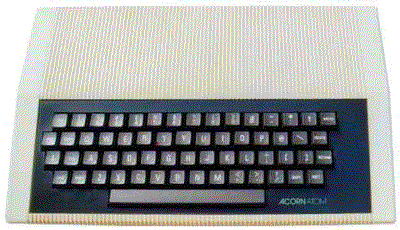
She's arrived! After many years of fussing and prevaricating I've finally
taken the plunge and bought myself an Atom. The prices were rocketing in
the bay of E, and I reckoned on the time being nigh. This one was
advertised as having a broken key and otherwise with little hope of
receiving a working box I decided on taking a punt and fixing it up if
necessary. I've always loved this machine. I owned one as a boy although
it was only a half-populated board without a case. It still did the
business though!
I must admit to being a little saddened when I
opened the wrapping. It was grubby and half of the keys appeared to be
smashed in, sitting a good 6-7mm lower than their neighbours. The 1st
thing was to open it up and check the power supply status. The Atom was
infamous for overheating and many owners bypassed the internal
regulators in favour of feeding it a regulated 5v diet.
|
|
As was indeed
the case with this one. It had received some tweaks in its time, but I
was really happy to see the work was all of a high standard. These were
all what I call 'magazine hacks' - the electronic equivalent of a
one-liner joke. Single wire patches for enabling an eighth bit on the
printer port, joining some lines to an external socket for wiring a
joystick, nothing major. I was chuffed to see that it was fully expanded
memory and support-chip wise. 12K RAM & 12K ROM plus a utility kit
that I'm still having trouble finding any info about. I'll have to
resort to a disassembler I think. No colour board but then I wouldn't
ever have even contemplated that. Too rare.
The mother and key
boards were in a real state. I think it had been stored on top of
kitchen cupboards at some point in its life and it had received a good
layering of yellow grease and fibres. Some keys were sticking and this
was the main reason. I've since scrubbed it with a toothbrush and plenty
of warm soapy water and now you'd never know! I was shy of putting it
in the dishwasher as some people recommend, this may be ok for generic
PC keyboards but rare vintage '80s hardware...
|
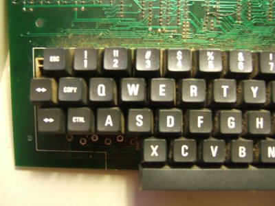 |
At some point in its history the three keys in the lower left had been
replaced. They were replaced with high quality keyswitches, which - well
I never - made the keycaps sit higher. What had happened was that the
previous owner had raised the original keycaps with superglue to match
the height of the replacements. The original mechanism is a cheap
spring-based creation which I've only ever seen in Atoms ... and a
keypad that I was given recently! That was handy, wasn't it! So I hacked
the keypad and replaced the switches with something contemporary and
far more suitable. And the same height! The caps all came off and were
cleaned and repaired where necessary.
The machine is now clean and tidy, ready for work.
One
tough trick was finding a plug to fit the odd power socket dimensions.
It's some olde fashioned imperial jack size. Eventually located with the
assistance of an Atom owning colleague I was able to juice the old
girl. To my immense surprise it eventually reset and presented me with
the very comforting words: ACORN ATOM > Joy!
|
A computer's no good without software, right? Like all good '80s machines
this one needs some square-wave goodness. I couldn't locate any
software to generate the required signals that worked on a modern PC, so
being handy with a compiler I got to work. I'm pleased I did all the
work on ACE - the techniques transferred instantly and I had a program
to translate raw program dumps into WAVS. And text files into raw dumps.
And vice versa.
I'll be happy to pass these on to anyone that wants them.
The source can be downloaded here.
It's vanilla C++. I'll be happy to help with porting, compiling or whatever.
There
looks to be a new site emerging that could eventually be a must-see for
any Atom fans. I'm speaking in the future tense as it's not there yet
but I've spoken with the masters and they're promising big things. |
|
|